

During firmware development, if something does not work as expected, we need to throw this question first: "hardware issue or firmware issue?" This idea will help to figure out potential root causes.
Hardware issue?
Verify power supply. Use a multimeter to measure each voltage test point such as 3.3V, 5V and 12V. Make sure the multimeter to DC mode and select right voltage range. Since it is DC, red probe goes to + and black probe goes to -(GND). If they are swapped, you would read negative voltage but magnitude would be the same.
Continuity check. Use a multimeter to verify electrical connections. https://www.fluke.com/en-us/learn/blog/digital-multimeters/how-to-test-for-continuity
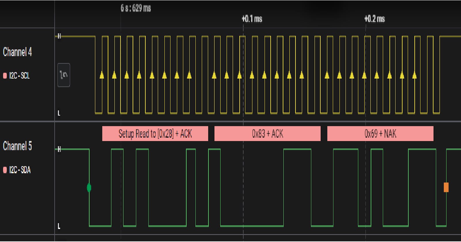
Verify serial communication. Use a logic analyzer to observe data line and clock line. Typically, the logic analyzer can decode UART, SPI, I2C and CAN messages.
Firmware issue?
Use a debugger to verify the code flow.
Verify clock configuration. The simplest way is using Systick and delay function with blinky application.
Use an example project from a microcontroller's vendor. This helps how to use vendor's driver code and pin configuration.
Here are the five steps of root cause analysis.(https://www.mindtools.com/ag6pkn9/root-cause-analysis)
Define the problem.
Collect data.
Identify causal factors.
Identify root cause(s).
Implement solutions.
Let's apply the root cause analysis to the firmware world example.
Problem: The force sensor does not provide the measurement.
Data
The sensor datasheet is found(https://www.te.com/commerce/DocumentDelivery/DDEController?Action=showdoc&DocId=Data+Sheet%7FFX29%7FA7%7Fpdf%7FEnglish%7FENG_DS_FX29_A7.pdf%7F20009605-23).
The sensor has four wires(Power, GND, I2C-SCL, I2C-SDA).
The sensor is communicated via I2C. The sensor is I2C slave and the microcontroller is I2C master.
The sensor supports the clock rate of 100kHz ~ 400kHz.
The sensor needs 3.3V DC power supply.
There are two commands(Measurement request and read data)
Casual factors
The sensor does not make a good connection with a target.
Wrong pin out
Connectivity issue
Firmware configures a microcontroller as I2C slave instead of master.
Firmware configures wrong clock rate.
The target board does not supply good power.
Firmware send wrong commands including frame format and slave I2C address.
Root causes
I2C-SCL does not make a good connection. To validate connectivity, measure resistance between I2C-SCL and GND. The measurement is close to 0 ohm. (root cause#1)
Firmware configures a microcontroller as I2C master correctly.
Firmware configures I2C clock rate as 100kHz which is within sensor's supported range.
Measurement is close to 3.3V.
Firmware configures a command with wrong frame format. (root cause#2)
Solution
Fix I2C-SCL wire.
Fix frame format and verify with a logic analyzer.
reference an example code based on Arduino project(https://forums.adafruit.com/viewtopic.php?t=179938). The datasheet did not provide details of commands.
Ask details of commands to TE customer service and receive another datasheet information(https://www.mouser.com/datasheet/2/698/REN_ZSC31014_DST_20160120_1-1999520.pdf).
As an engineer, the problem solving is life. To solve problems more efficiently, we need a method which can guide us to make a problem more specific and quantitative. One of methods is the root cause analysis and I show how to apply this method over real firmware problem above. While writing down the root cause analysis, everything becomes more clear. At the end, I am able to read force value!