

- CAN?
CAN stands for Controller Area Network. In OSI model, CAN is physical layer and data link layer. This is defined in ISO 11898. It is widely used in various fields such as commercial vehicles, tractors, medical devices, industrial automation and etc. Many devices can be connected to CAN bus and able to communicate each other. If one device sends a message on CAN bus, all devices on the bus will receive the message. It is broadcasting. In application, you can set message ID filter to control number of messages per device to handle.
- CAN transceiver
There are many CAN transceivers in the market which can interface between CAN bus and a microcontroller. A CAN transceiver TX/RX pins are connected to microcontroller's CAN TX/RX pin. The CAN transceiver CAN High/Low pins are connected to CAN bus.
- CAN High/Low pin?
During communication, CAN High pin will produce high voltage and CAN Low pin will produce low voltage. This state is called Dominant. During no communication, both CAN High pin and Low pin produce nominal voltage about 2.5V. This state is called Recessive.
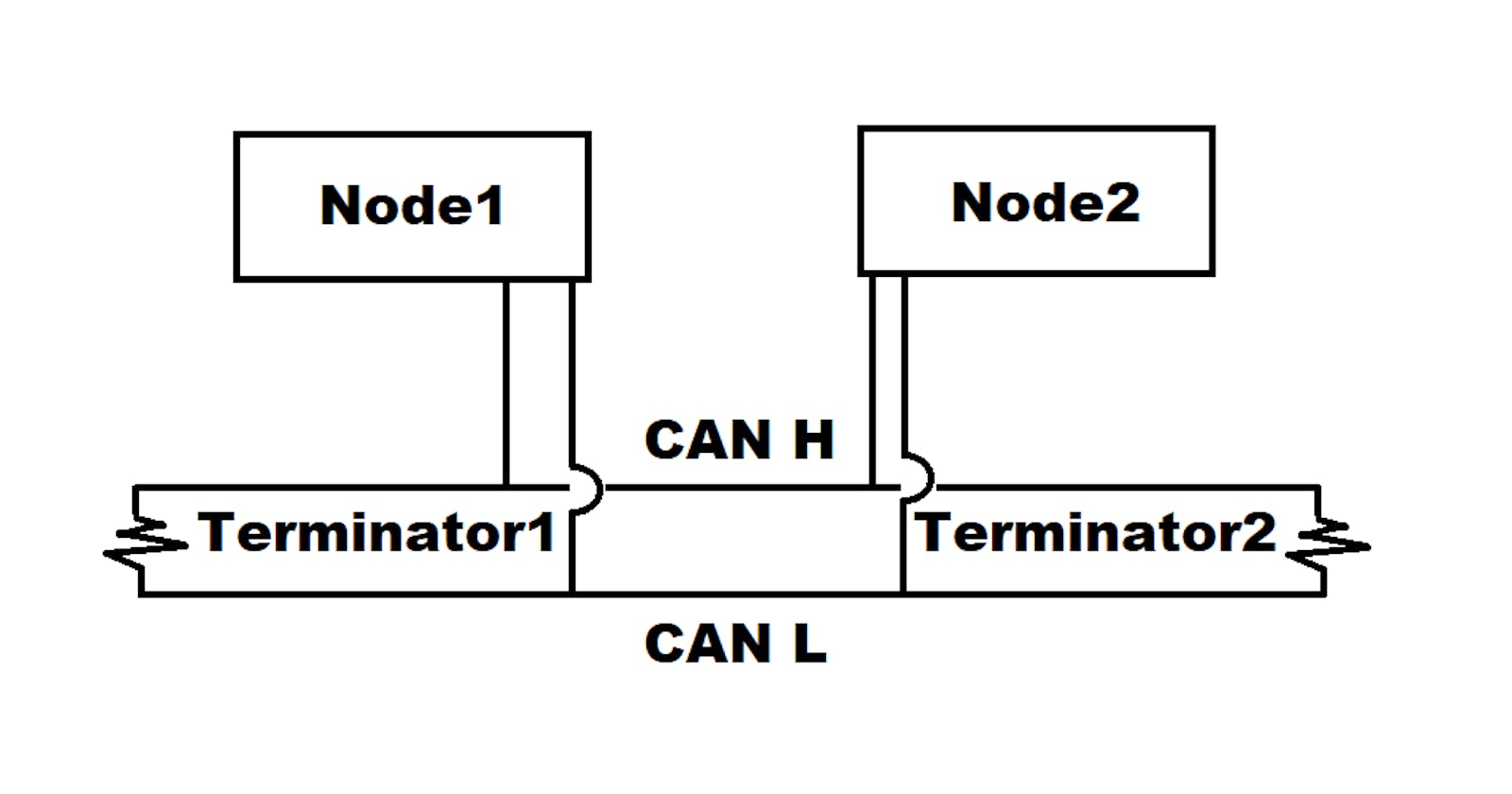
- CAN bus terminator?
CAN bus is required to have two terminators each end of bus. Because of this specification, typical CAN bus topology looks like below:
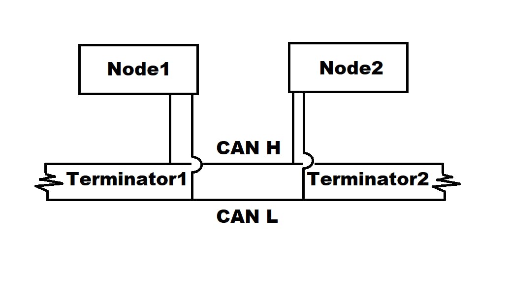 The terminator is nothing special but a 120 ohm resistor.
- EMC consideration for CAN bus terminator
There are two more options other than standard termination.
- Split Termination - split into two 60 ohm resistors, with a bypass capacitor tied between the resistors and to ground.
- Biased Split Termination - adding voltage divider circuit to achieve a voltage of VDD/2 between two resistors from Split Termination.
(Reference: AN228 page 9-10, Microchips)
- CAN bus cable length and speed relationship?
According to ISO11898,
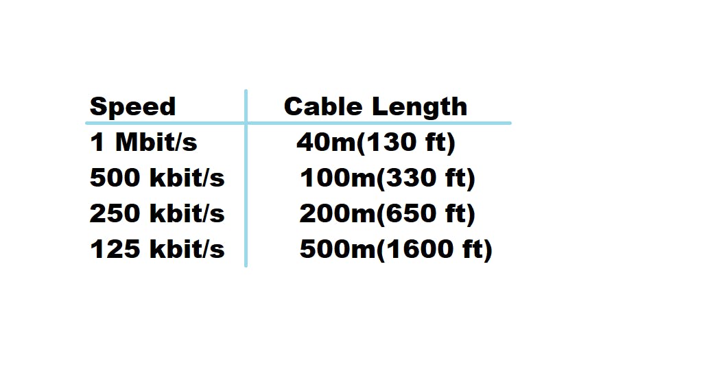 As you can see faster speed can achieve shorter cable length. Why? To comply with the transceiver's propagation delay. The CAN protocol has defined a recessive (logic ‘1’)
and dominant (logic ‘0’) state to implement a nondestructive bit-wise arbitration scheme. Longer propagation delay will break arbitration scheme. (Reference: AN228 page 4, Microchips)
As you can see faster speed can achieve shorter cable length. Why? To comply with the transceiver's propagation delay. The CAN protocol has defined a recessive (logic ‘1’)
and dominant (logic ‘0’) state to implement a nondestructive bit-wise arbitration scheme. Longer propagation delay will break arbitration scheme. (Reference: AN228 page 4, Microchips)